1. What is a Cut Over
A cutover is the controlled process of transferring live network traffic from an existing (legacy) fiber infrastructure to a new one. Unlike a fresh installation where no services are running, a cutover happens on a live network — customers are actively using the circuits being moved. This makes it a high-stakes operation where every minute of downtime matters.
Cutovers are required in several scenarios:
- Migrating subscribers from an old fiber route to a newly built route
- Replacing damaged or degraded cable segments with new cable
- Upgrading network architecture (e.g., moving from a point-to-point to a PON design)
- Relocating infrastructure due to construction, road work, or utility conflicts
- Consolidating multiple fiber paths into a single optimized route
Key principle: A cutover is NOT an installation. It is a transition. The new infrastructure must be fully built, tested, and validated BEFORE the cutover window begins.
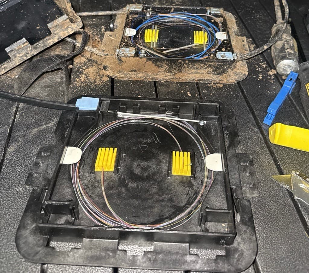
Old and new PLP side by side during a cutover migration
The goal of every cutover is zero or minimal service interruption. In practice, this means the actual downtime window — the time between disconnecting the old fiber and lighting up the new fiber — should be measured in minutes, not hours.
2. Pre-Cutover Planning & Checklist
A successful cutover is 90% preparation. The following steps must be completed before any live traffic is moved.
2.1 Scope Definition
- Identify every circuit, customer, and service affected by the cutover
- Document the exact fiber pairs being moved (old route → new route)
- Determine the number of splices, connectors, and enclosures involved
- Confirm whether the cutover is a full cable swap or individual fiber migration
2.2 New Infrastructure Validation
Before scheduling the cutover, the new fiber path must pass these tests:
- OTDR testing — End-to-end trace on every fiber in the new cable. Verify splice losses are within spec (typically ≤ 0.1 dB for fusion splices). Document all events.
- Insertion loss testing — Measure total link loss with a calibrated light source and power meter. Compare against the calculated loss budget.
- Connector inspection — Every connector in the new path must be cleaned and verified. Clean and re-test until pass criteria are met.
- Continuity verification — Use a VFL (Visual Fault Locator) to confirm fiber routing and polarity on every fiber pair.
- Label verification — Confirm all splice trays, enclosures, patch panels, and fiber assignments match the design documentation.
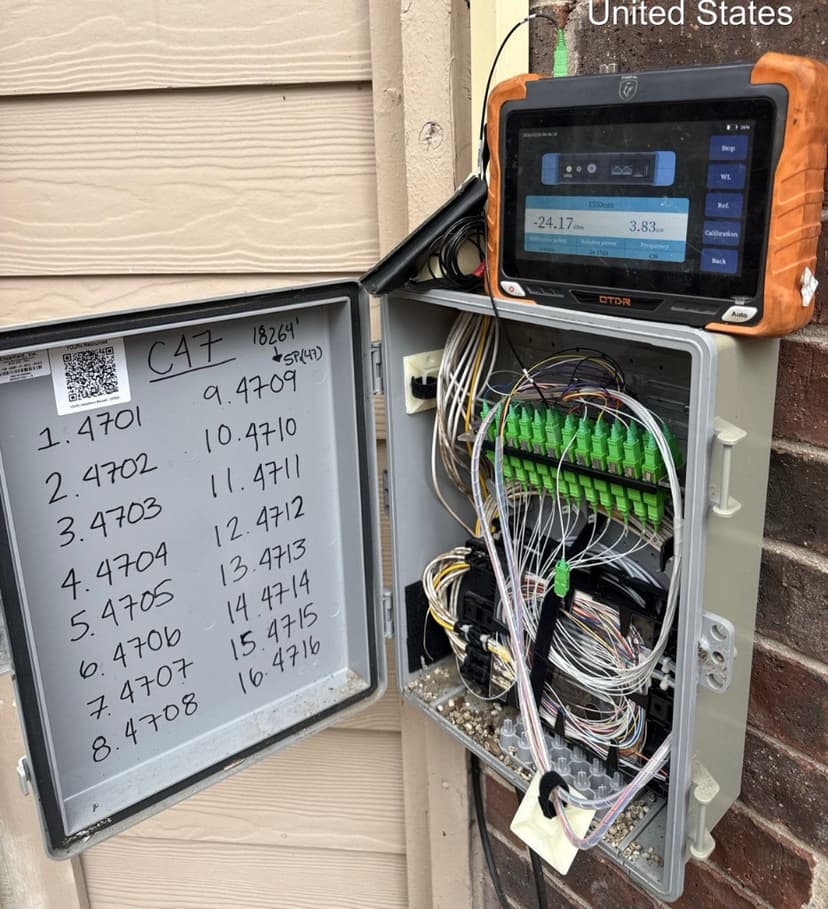
OTDR verification at NDP
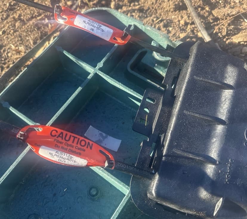
Label verification — IN/OUT tags
2.3 Cutover Runbook
Create a detailed runbook document that includes:
- Step-by-step sequence of operations (numbered, no ambiguity)
- Assigned roles: who performs each step, who verifies
- Communication plan: who is notified at each stage (NOC, customer, PM)
- Timing: estimated duration per step, total cutover window
- Rollback trigger criteria: specific conditions under which you abort
- Contact list: every person involved with phone numbers
2.4 Pre-Cutover Checklist
- 1New fiber path fully built and spliced
- 2OTDR traces completed and saved for every fiber
- 3Insertion loss test passed on every fiber pair
- 4All connectors inspected and cleaned
- 5Labels verified against design documents
- 6Cutover runbook written and reviewed by lead tech
- 7Customer / NOC notification sent with maintenance window
- 8Rollback plan documented and understood by all crew
- 9All tools and test equipment staged at cutover locations
- 10Spare fibers, splice sleeves, and enclosure hardware on-site
- 11Communication channel established (radio/phone/group chat)
- 12Weather and site access confirmed
3. Day-of Execution — Step by Step
On cutover day, follow the runbook exactly. No improvisation. Every step is performed, verified, and acknowledged before moving to the next.
Step 1 — Pre-Start Briefing
- Gather all crew at staging area. Review the runbook together.
- Confirm roles: who is at which location, who calls what, who is lead tech.
- Verify all tools and equipment are present and functional.
- Confirm communication channels are working (test radio/phone).
- Verify the maintenance window is active and NOC is aware.
Step 2 — Final Pre-Cutover Tests
- Run a final OTDR trace on the new fiber path — compare to baseline.
- Verify light levels on the existing (old) path as a baseline for comparison.
- Confirm all splice enclosures on the new path are sealed and secure.
- Take photos of all connection points before any changes are made.
Step 3 — Notify and Confirm Go/No-Go
- Contact NOC / project manager: "We are ready to begin cutover."
- Wait for explicit GO confirmation before proceeding.
- If any pre-cutover test failed → do NOT proceed. Execute rollback.
- Log the exact time of GO confirmation.
Step 4 — Disconnect Old Path
- At the designated splice point or patch panel, disconnect the old fiber pairs.
- Work in the sequence defined in the runbook — one circuit at a time when possible.
- Immediately protect disconnected fiber ends with dust caps.
- Log the exact time of each disconnection.
Step 5 — Connect New Path
- Connect the pre-tested new fiber pairs at the patch panel or splice point.
- Clean every connector immediately before mating — even if cleaned earlier.
- Verify polarity (TX → RX) on every connection.
- Log the exact time of each connection.
Step 6 — Immediate Light-Level Verification
- As soon as connections are made, measure receive power at the far end.
- Compare to the expected value from pre-cutover loss budget calculations.
- If power is within spec → proceed. If not → troubleshoot immediately.
- Report light levels to NOC / PM.
Step 7 — Service Verification
- NOC or customer confirms services are operational on the new path.
- If multi-circuit cutover, verify each circuit individually.
- Do NOT close splice enclosures or leave the site until all services are confirmed UP.
- Log confirmation time for each circuit.
4. Post-Cutover Verification
After all services are confirmed up, perform these verification steps before leaving the site:
4.1 Testing
- Power meter check at NIU — Measure receive power at the NIU with VeEX. Must be above LL threshold for the technology (GPON: -22.0 dBm, XGS-PON: -22.0 dBm, Go-Long: -28.0 dBm).
- OTDR trace on the completed cutover path — Run OTDR to verify all splice losses are within spec. Compare to pre-cutover traces if available.
- Service-level verification — Confirm with NOC that all circuits are passing traffic normally, bandwidth is nominal, and no alarms are present.
4.2 Physical Inspection
- All splice enclosures properly sealed (IP68 rating maintained)
- All patch panel connections seated fully, dust caps on unused ports
- Cable routing is clean — no kinks, no tight bends, proper radius maintained
- All cable ties and supports installed, no hanging or unsupported cable
- Old (decommissioned) fibers properly capped, labeled as inactive, or removed
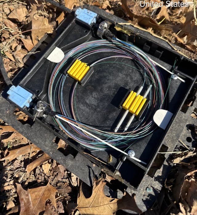
PLP — organized splice tray
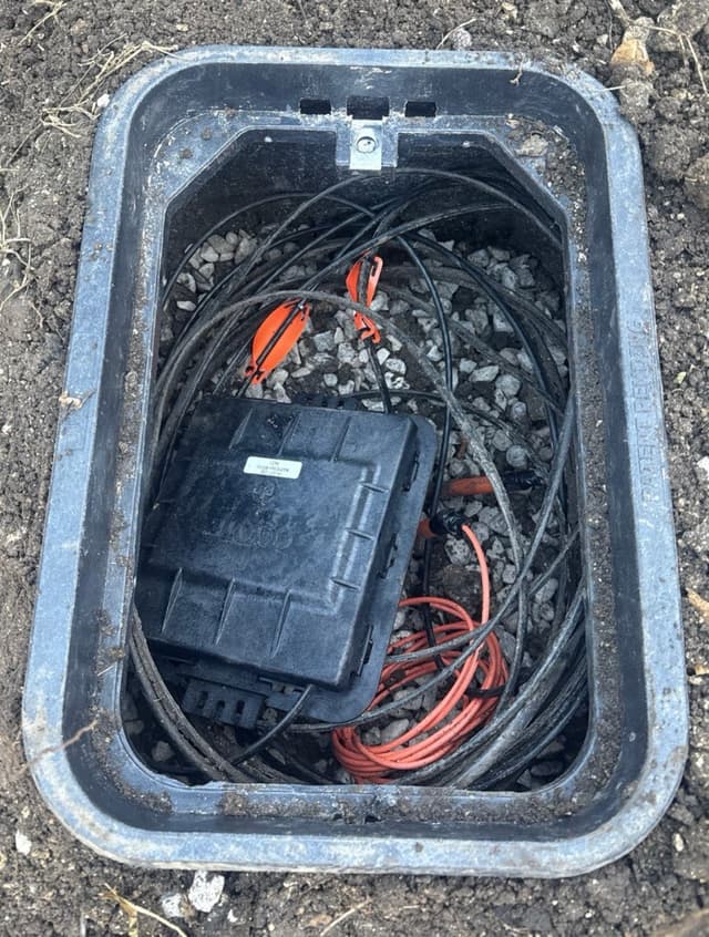
Vault — PLP secured inside
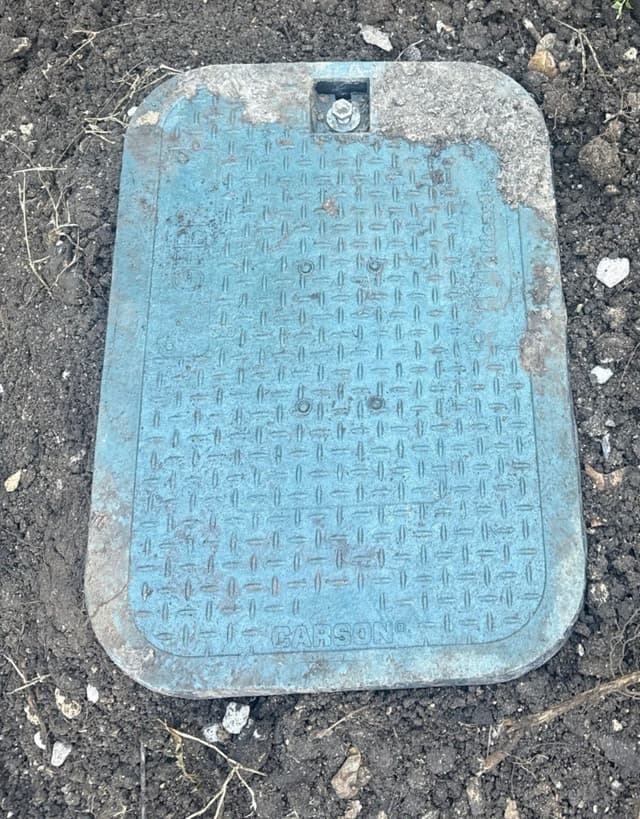
Vault lid closed and bolted
4.3 Soak Period
After the cutover, NOC monitors the new path for 10–15 minutes. If all circuits come back up clean — no alarms, no loss, levels are good — it's hands off. You're done.
- Stay on-site during the soak — NOC may need you to re-check a port or clean a connector
- If something doesn't come up, troubleshoot immediately while the MW is still active
- Once NOC confirms all clear, pack up and close the ticket
5. Rollback Procedures
A rollback means reverting to the old path. It is a safety net, not a failure. Knowing when and how to rollback is a critical skill.
5.1 When to Rollback
Trigger a rollback if any of these conditions are met during or after cutover:
- Light levels on the new path are outside acceptable range and cannot be remediated on-site
- Services do not come up within the defined maintenance window
- Multiple circuits fail simultaneously on the new path
- Physical damage is discovered on the new route during cutover
- Project manager or NOC explicitly calls for rollback
5.2 Rollback Steps
- Announce to all crew and NOC: "Initiating rollback."
- Disconnect the new path connections.
- Clean the old fiber connectors (they should still have dust caps from Step 4).
- Re-connect the old fiber pairs in the original configuration.
- Verify light levels on the restored old path.
- Confirm with NOC that services are back to normal on the old path.
- Log all rollback times and reasons.
- Conduct a debrief to determine root cause and plan re-attempt.
6. Documentation & Closeout
Every cutover must produce a complete documentation package. This is not optional — it is how future crews maintain the network.
6.1 Required Documentation
- Cutover completion report — Summary of what was done, when, by whom
- OTDR traces — Pre-cutover (baseline) and post-cutover for every fiber
- Insertion loss test results — Per-fiber actual vs. budgeted loss
- Splice records — Splice tray diagrams showing old-to-new fiber mapping
- Photos — Before and after at every work location
- As-built drawings — Updated route maps reflecting the new configuration
- Time log — Start/end of each step, total downtime per circuit
- Issues log — Any problems encountered and how they were resolved
6.2 Handoff
Deliver the documentation package to the project manager and network operations team. Confirm that all as-built records in the GIS/mapping system have been updated. The cutover is not complete until documentation is accepted.
Field Standards
LL thresholds, splice & connector criteria, attenuation tables